3D machining - Overview
1 - What is 3D Machining in CamBam?
Operations like profiles and pockets are called 2.5D operations, because the machining can follow a 2D shape (XY plane) but without variation of the depth in Z apart from the step increments ; we can therefore only make shapes with a flat bottom, based on a 2D contour.
With 3D machining, the tool can follow a variation in height in Z of a 3D object which will therefore make it possible to machine shapes such as slopes, domes and all non-flat shapes.
In the case of CamBam, a 3D machining necessarily involves the use of a 3D mesh object as the basis of the 3D machining operation.(.stl or .3ds format, and also .step in CamBam V1.0)
For example, the area in purple of this part will have to be machined with 3D machining because the other machining modes would not allow to generate a Z curvature.

It is possible to restrict the area to be machined in 3D using 2D polylines as boundaries. In the case of the part above, we would therefore use the usual profile, pocket and drilling operations to obtain the basic shape as below,

then would come one or more 3D machining operations to machine the area in purple by restricting the area to be machined in XY to an area covering almost the top surface of the part.
On the contrary, parts like below, would need to be made entirely in 3D machining.


2 - Operating principles of 3D machining
A 3D machining operation in CamBam can use 2 very different operating principles, each with their advantages and disadvantages, but also their limitations depending on the shape of the workpiece.
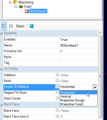
These 2 machining modes are called Scanline mode (horizontal or vertical) and Waterline mode (roughing or finishing)
Obtaining good results in terms of precision, speed and surface finish will largely depend on a judicious choice between these 2 types of machining modes depending on the shape of the part.
Often, both modes will have to be used on the same part to obtain the best possible result in the shortest possible time.
3 - Scanline machining
The principle is simple, the machine performs a horizontal or vertical scan of the part and the tool moves up and down (Z axis) to follow the surface of the 3D object.
The parameters which influence the quality of the restitution of the model.
The StepOver:
The lateral distance between the passes is given by the StepOver property of the machining operation; here it is 0.6, i.e. 60% of the diameter of the tool used (3mm ballnoze tool ; the part is 40x60x26 mm)
the simulation result (horizontal scan)

To obtain a better result, both in surface finish and in model tracking accuracy on the axis perpendicular to the scanning direction, a lower StepOver can be used; on the following images, it is 0.2. As I am using a 3mm tool, it is therefore 0.2 x 3 = 0.6mm between passes.

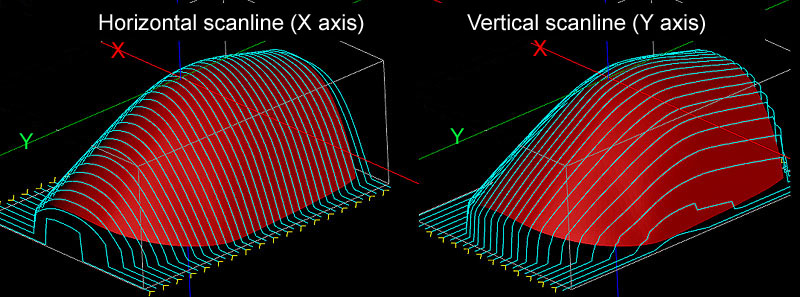
Note also, as can be seen in the following image, that the direction of scanline in relation to the slope of the part also has a great influence on the result.

On the bottom picture, the fact that the toolpaths are almost parallel to the plane of a strong slope gives very marked stairs on this area of the part (StepOver = 0.4 in both cases)
and finally, a double horizontal + vertical scanline, always with an StepOver of 0.4 (2 separate operations, identical except for the orientation of the scanline)

The resolution
The toolpaths that we see on CamBam's display are in fact nothing more than polylines, made up of a number of straight segments.
In the following image, we see one of the paths that I converted to a polyline; each red square is a point on the polyline that delimits a segment. When creating the Gcode each segment will be converted into a Gcode line. We understand why 3D machining Gcode are generally bulky.

As for the StepOver, the Resolution will therefore determine the accuracy of the shape tracking, but this time along the toolpaths.
The Resolution is also expressed as a fraction of the tool diameter; here after converting the toolpaths into a polyline, we see the result with a resolution of 0.6 and a 3mm tool, ie a resolution of 1.8mm.
To create a toolpath, CamBam will therefore take a height measurement of the 3D shape every 1.8mm along the path.
The following image shows this principle; we can clearly see that all the "nodes" of each path (converted into a polyline to see them) are aligned with a "grid" with a pitch of 1.8mm corresponding to the requested resolution. In the case of flat areas, CamBam will optimize the path by removing unnecessary knots.

Another example which gives an idea of the influence of the resolution.
the bosses of this part are 2mm in diameter, and here are the toolpaths obtained according to the resolution (always with a 3mm ballnoze tool).

in light blue, the toolpath with a resolution of 0.03 (i.e. a horizontal spacing of 0.09mm with a 3mm tool), in yellow with a resolution of 0.2, and in red with a resolution of 0.5
The fact that even the path in blue does not follow the shape is of course normal, the path takes the profile of the ballnoze tool into account. The path represents the position of the end of the cutter in its center, as indicated by the arrow in the following image.

the simulation results for these 3 resolution settings with always a cutter of 3.

This shows us that if the resolution is insufficient, details of the part will be "erased" or "distorded" because the path will not have enough bend points to conform to the shape as well as possible.
Another disadvantage of insufficient resolution will be the detection of an almost vertical surface; the lower the resolution, the more the vertical flanks will have a slope instead of a vertical flank. It is inevitable, the slope will be directly related to the horizontal spacing of the points forming a polyline segment constituting the tool path; this distance being itself given by the resolution.

The Scanline mode is therefore not very comfortable with shapes having almost vertical sides.
Roughing and finishing in Scanline mode
In Scanline mode, if the Roughing/Finishing property is set to Finishing, only one pass at maximum depth will be made, as in the previous images of the cockpit windows. If this parameter is set to Roughing, the value of Depth Increment will be used and the model will be machined in several levels.
4 – Waterline Machining
This 3D machining mode allows the use of a Waterline Rough mode and a Waterline Finish mode in Profile 3D Method ; these 2 modes have a slightly different behavior even if they are based on the same operating principle.
If a waterline mode is used in Profile 3D Method, the part is "sliced" horizontaly and the tool machines the equivalent of a profile (finish) or a pocket (roughing) at different levels; there is thus no displacement in Z simultaneously with the movements in XY. It's actually a bit the same principle as 3D printing.
Waterline Finish mode
An example of the same part with toolpaths with Waterline Finish mode

In this case, the vertical spacing between the passes will be given by the Depth Increment.
This operation works like a profile operation, but each machining level has its own outline defined by the shape of the 3D object at the current level. Here the Depth Increment is 2mm and as we can see that the result is very different from the scanline mode.
On the following simulation one can sees the impact of the Depth Increment on the result; left 2mm, right 0.6mm (Ø3 Ballnoze cutter)
The Depth Increment is therefore the counterpart of the StepOver in scanline mode, it is this which will determine the finish and the smoothness of the part.

on the following images, we can also see the influence of the slope of the part on the result obtained and realize that, unlike the scanline mode which is not comfortable with vertical surfaces, here, it is the surfaces which are not very inclined from the horizontal which pose a problem.
To the right side of the part, it would take a smaller Depth Increment to smooth the part, and the almost horizontal top is impossible to cut with this method unless you use an extremely low Depth Increment. (but there will always be a "nipple")

On the following image we can clearly understand the reason for this result; the lower the slope, the more the space between toolpaths increase, until they disappear in the event of a completely flat area.

In the Waterline Finish mode, the resolution has a different meaning from the scanline mode; it determines the level of precision of the curvature of the ballnoze tool that will be used to calculate the toolpath compensation.
The formula used is as follows:
Number of measuring points on the radius of curvature of the ballnoze tool = 1 / resolution
A resolution of 0.2 will therefore give 1 / 0.2 = 5 measuring points at the radius on the rounded part of the tool, so 10 on the entire curvature of the end of the tool. (plus the tip point at the tool end)
These measuring points are not distributed uniformly on the curved part, but on the tool radius and are then projected on the curvature. The approximate shape of the tool will look like the green line in the image below. In all cases, the approximation error will have the effect of leaving more material, rather than removing too much.

In practice, the larger the diameter of the tool, the more it is desirable to increase the resolution in order to have good tracking precision of the 3D model, but beware, this considerably increases the time for calculating the toolpaths !
Waterline Finish mode can handle Ballnoze and Endmill tool profile. (With Endmill, the toolpath calculation is faster, but that leave stairs on the part)
Waterline Rough mode
As in Finish mode, Rough mode will slice the part horizontaly at each machining level (Depth Increment), but instead of just making the outlines, it will perform the equivalent of a pocket machining delimited by these level lines.
here is the workpiece to cut

In the images which follow, we must imagine that the part is in the water and that we lower the water level by stages (1 stage = Depth Increment). Anything left in blue will be machined for each level.

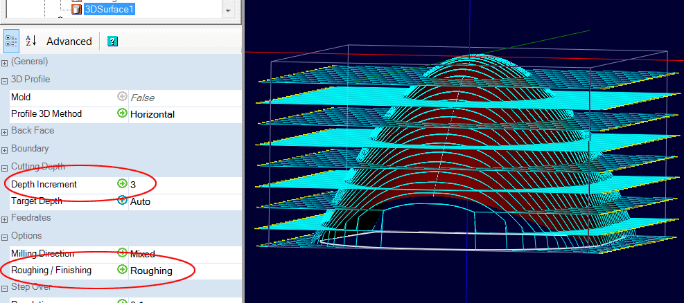
The following image shows the result obtained with a Depth Increment of 3mm and a tool of 4mm.

a video showing the different toolpath in CamBam.
As can be seen in the image, the machining produces a stair shape whose height of the stairs depends on the Depth Increment and the bottom of the "pockets" has no curvature.
The interest of this roughing mode is mainly due to the fact that for certain 3D shapes, it allows a faster roughing than the scanline mode, but more approximate. It does not manage ballnoze tools but only endmill tools. (no compensation for the ballnoze tool profile, only for cylindrical tools) but this is not a problem because if you want a rapid roughing, the use of a ballnoze tool is not recommended (lower feed per tooth on a ballnoze tool than on a cylindrical tool)
Typically, a Waterline roughing is used if the part geometry is suitable, followed by a Scanline finish or a Waterline Finish depending also of the part geometry. Of course, in the roughing operation, an extra thickness of material will be left for the finishing. (Roughing Clearance)
Advantage of a Waterline roughing compared to a Scanline roughing.
In some cases, it is possible to speed up the roughing phase if the part has a suitable configuration by using the Waterline Roughmode.
We will take this part as an example

The following animation shows the different machining levels in Scanline mode.

We can see that at each machining level, the tool goes back to the left side of the part, which is however already at the finished dimension from the first pass, which wastes time unnecessarily.
On the contrary, a Waterline Rough will make a series of pockets more economical in machining time.
In the example given, with the same Depth Increment, the same StepOver and of course the same feed rate, the roughing is done in 29:45s in Scanline mode and in only 15:41s in Waterline mode.
A roughing in Waterline mode on the same part.

Of course, here it is a textbook case; it would be easy to restrict machining to the "bottom" area using a polyline defining the boundary of the machining area. (Boundary Method: Selected shape), but often, on a real part there can be several different areas with different height differences, and it is easier in this case to rough using the Waterlines method.
5 - Finishing, Waterline or Scanline ?
To be continued, please be patient !