Nesting
CamBam allow to repeat a series of machining operations at different positions on the machine table. It is possible to get multiple copies of a workpiece with a single design and only one set of machining operations.
The nesting operate on the contents of an entire part, all machining operations contained in a part will be machined at the positions defined in the properties of the nesting section for the part. The order in which operations are performed is configurable.
Implementation of a nesting
You must first create one or more machining operations.
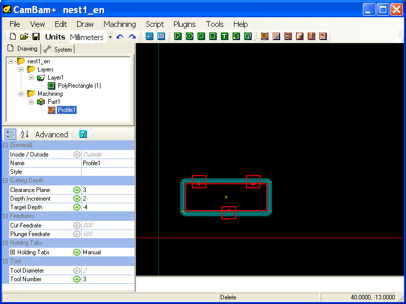
For the first example we will use a single operation, an external cut of a rectangle of 10 x 30 mm with a tool of 2 mm diameter.
The Profile operation set and view with tabs and width of the tool.
Setting the nesting
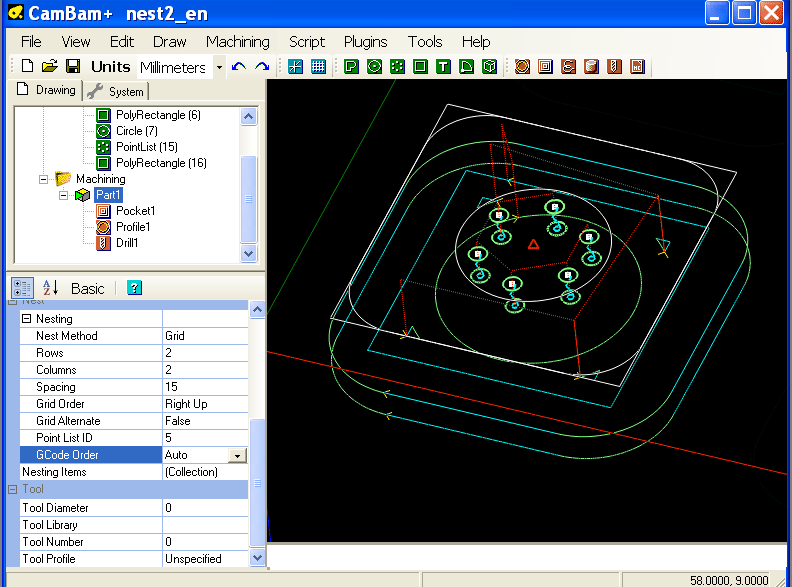
All the properties defining the nesting are located at the Part folder.
Select the Part containing the Machining Operations (MOP) that must be nested for display the settings.
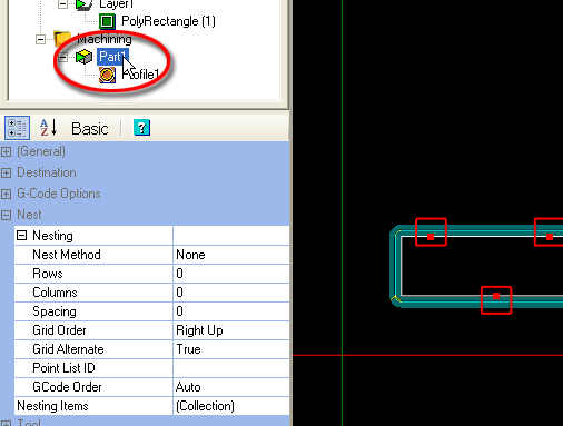
Click the + sign next to the word "nesting" to display all options.
Nest Method
The Grid and ISO Grid methods are used to distribute copies of machining operations in rows and columns automatically. The ISO Grid method additionally adds a horizontal / vertical shift of half the pitch at each row / column.The shift is performed on the lines or the columns depending on the value of Grid Order.
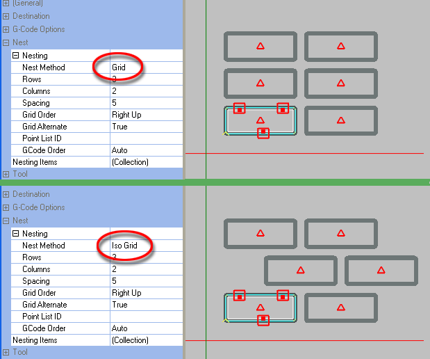
You can also activate the menu View/ Show cut widths, allowing a better view of the copies as on the images above ..
To create the nesting of this example, select a type of grid, enter the number of Rows and Columns you want, a Spacing value, and then generate the toolpaths of the Part via its context menu.
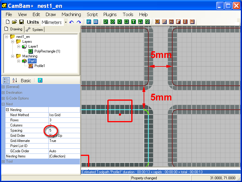
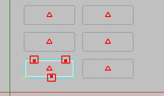
In the picture above (reworked to properly view the toolpaths) you can see the distance of 5 mm between the toolpaths and the width of 2mm of the cutter. (Show cut widths)
Grid order
Controls the direction of the grid layout. For example Right Up will make copies to the right of the original, then move up to the next row.

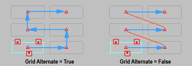
Grid Alternate
If set to True, the grid will alternate the direction of each row or column (depending on Grid Order). If False then each row or column will proceed in the same order with a rapid back to the start of each.
Moving the copies
You can move the copies manually.
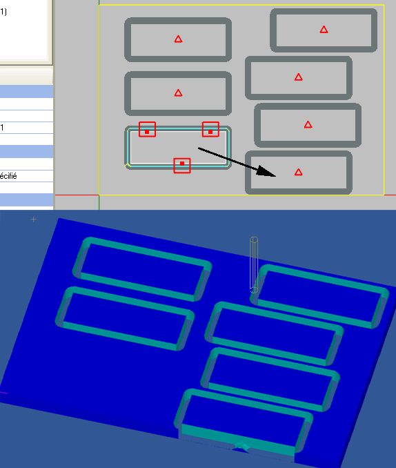
Click and hold the left button of the mouse over the red triangle of a copy and move it to the desired position. The nest method will automatically switch to manual.
Note that if you move the original copy, the original will always appear at the same position on the display (but without the red triangle). but will not be machined as the image of the simulation below shows (the black arrow indicates the displacement of the original)
You can also edit the location of copies, delete or add, modify the order in which they will be machined using the Nesting Item collection editor.
Set the Nest Method to Manual, and then edit the (collection) object. (you must be in Advanced mode to access)
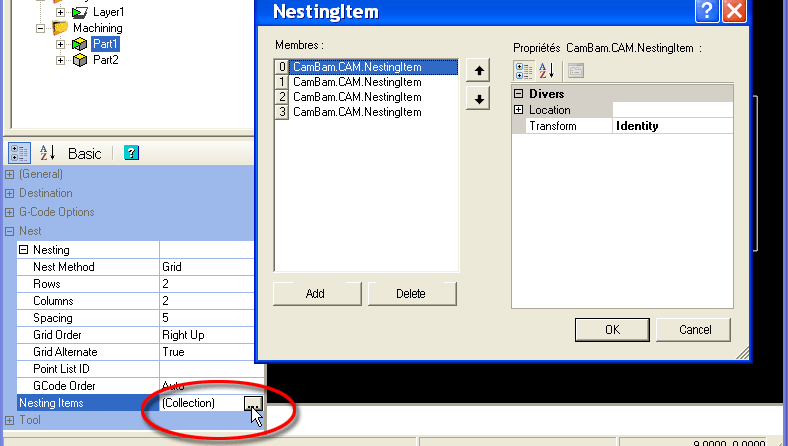
The left part of the window allows you to add or remove copies using the Add and Delete buttons.
With the two vertical arrows to the right of the list you can change the order of the list, and thus the machining order of the copies. (select a copy then clic on arrow to move up or down)
The right part of the window allows you to edit the coordinates of each copy.
Using a points list for define a nesting
It is possible to use a points list for define the respective positions of copies by using the Nesting Method set to Point List, and then assigning the ID of the point list in the Point List ID property.
The original coordinates of the nesting system are always at the drawing origin, at the center of the X and Y axes. (or in the center of the small cross indicating a new origin, if it has been modified in the Machining folder)
The image below shows the points corresponding to different copies.
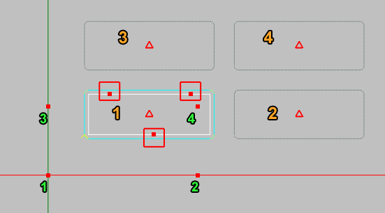
It is also possible to generate a list of corresponding points to an existing nesting. This is what I did to get the point list corresponding to the different copies of the image above.
Copies having been previously created with the automatic placement obtained with the Grid method.
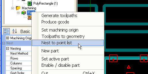
For create this point list, open the context menu of the relevant Part, and use the menu item: Nest to Point list
Why use a point list ?
There are some cases where the use of a Point list is required.
- If you want to assign a value from center to center distance between the copies rather than spacing between them. (or more precisely, between the outermost toolpaths)
- If you need a specific placement, which can for example be the result of a mathematical calculation. The point list can be created in a spreadsheet and then imported into CamBam.
- If you use several different Parts that need the same placement.
In this case the spacing between copies is not usable because it is based on the distance between the outermost toolpath of the Part, and of course, the outermost toolpath can be different from one Part to another, depending on the machining operations that compose it.
In this case you must use the same list of points for all Parts that must have an identical positioning of their copies.
Use the Nest to Point list function on the Part that give the suitable placement. then assign this point list to all other Parts that must use the same nesting pattern
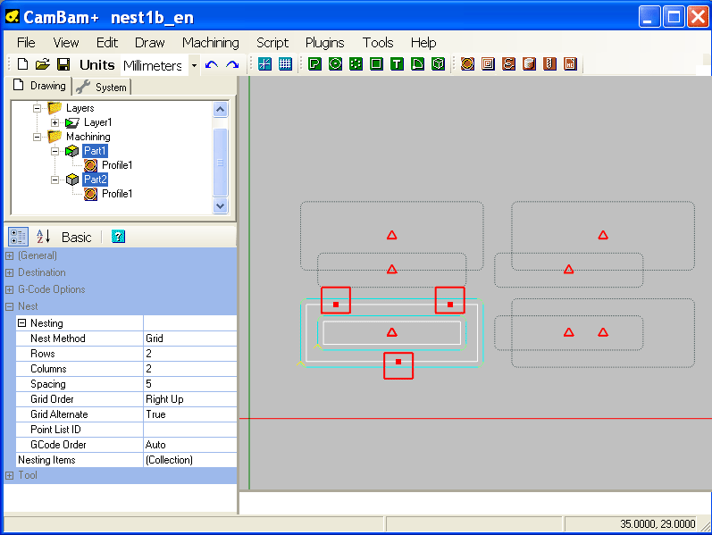
In this image, the nesting with the Grid method is used with the same parameters for both Parts properties, and as you can see, the operations of the second Parts (the small rectangle) are not executed in the right place.
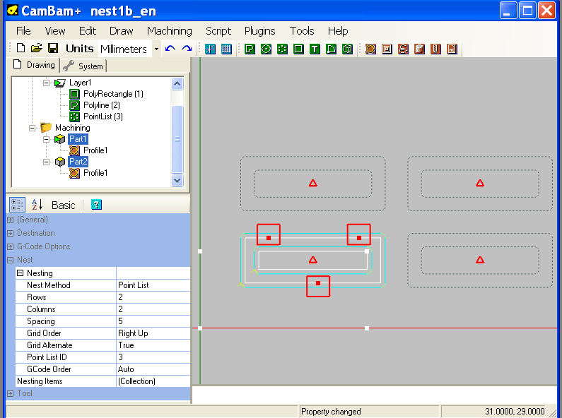
After generating a point list for "Part1", and assigning this point list to the both Parts, everything is in order. (you must also switch the Nest Method to Point list )
Output order of machining operations
The GCode Order property is used to select the order in which operations contained in a Part are executed when there are more than one machining operation.
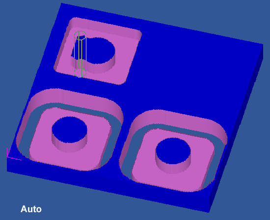
In the following example, the machining "Pocket1" (an island) and the cutting "Profile1" are machined with the same tool of 8mm diameter, the operation "Drill1" is performed with a tool of 2mm diameter, so there is a tool change at the beginning of the "Drill1" operation .
Auto - All consecutive MOPs within the part with the same toolnumber will be posted then repeated for each nest copy, before moving to the next MOP (which would require a tool change).
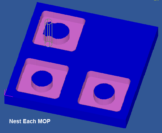
Nest Each MOP - Each MOP is output at each nest location before moving to the next MOP.
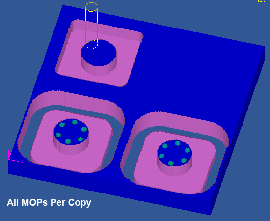
All MOPs Per Copy - All the MOPs in the part are posted before moving to the next nest location.
Use of the nesting with a 4th rotary axis
To use the nesting system with a rotary axis to reproduce the same machinings at different angular positions, just use a point list containing the same number of points as the number of copies to be made but with all points with X and Y coordinates set to 0.
The machining operations in the Part will therefore repeated at the same place and just add a little of Gcode in the Custom MOP Footer of the last machining operation of the Part for rotate the 4th axis of the desired angle before performing the following sequence of machining operations.
example:
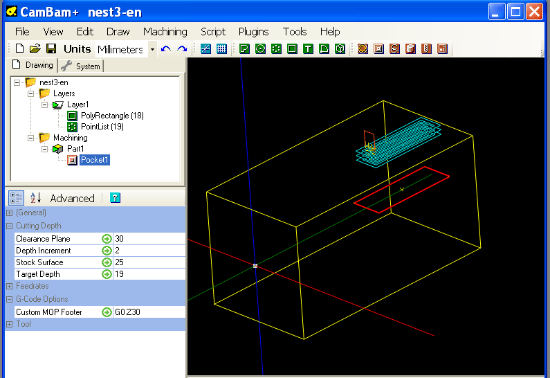
To machine 6 grooves distributed around a shaft of 50mm diameter.
I create a Pocket operation with a value of Stock surface equal to the radius of the workpiece to be machined, in this case Stock surface = 25 (Z=0 is set at the axis of the chuck on the CNc)
I create a Point list with 6 points, all at 0,0,0
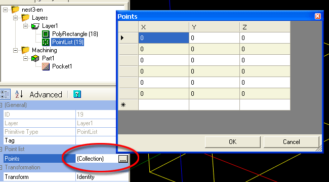
I define a nesting with the Nest method = Point list for this Part, then I assigns to it the point list that I just created.
My pocketing will be repeated six times in the same place.
To rotate the chuck at the end of the part's operations, I added the following Gcode sequence in the Custom MOP Footer property of the last machining operation of the Part.
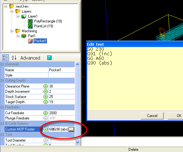
G0 Z30 -> go back to the clearance plane
G91 -> use relative coordinates so as to give a rotation angle rather than an absolute position.
G0 A60 -> rotate the A axis of 60 ° (360/6)
G90 -> back to absolute coordinates.
The result can not be seen in CamBam nor CutViewer, but it appears clearly in the Mach3 simulation window .

To see the list of properties of the nesting system, clic HERE